|
|

THIS SPACE IS FOR FINISH AMPLIFIER PICTURE |
|
|
|
Boring Stuff:
Here's another amplifier project of
mine. And still learning lots of thing as I build. I suddenly
got the Six Meter bug so why not build a 6 meter amplifier. I
did lots of research on Six meter amps and look at all the
different designs and schematic I could fine. And with that I
will try an incorporate some of these into my own project.
If your thinking of building your first
amp. Be prepare to do a lot of metal work, and this is were
you'll be spending a lot of time. And be sure to plan out your
project as much a possible. It will help I
you throw out your project.
The first thing I've learn when starting
a amplifier project is to decide on what tube or tubes your
going to use. And then start with your power supply section.
The transformer for this project came from a old beat up
Heathkit SB-200 amp I've had for 20 some years. Also made use
of other parts from this amp.
Tube's for this project is a pair of
Russian GI7B tubes. Ok so Let me get started. One thing you
need to do before using these tubes is to burn in the filament
for at lease 48 hours before applying
any High voltage to them.

|
|
|
Power
Supply:
The first
part of this project is to build the power supply
section and get it all working correctly. The
transformer is from my beat up old Heathkit SB-200
amplifier. The capacitor and rectifier board is also
from the Heathkit SB-200 amp along with the breaker.
Since I decide not to re-build it, I decided to make use
of the parts.
The
transformer was check out and still working. I then
clean it up and repainted it. The
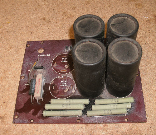
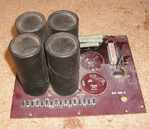
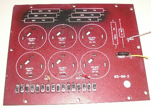
filter capacitor and rectifier PCB is being re-used. I
remove all the components and clean up the board.
Image 1 shows the PCB before removing all of the
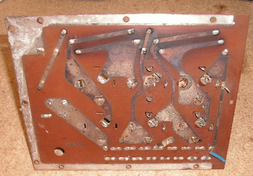
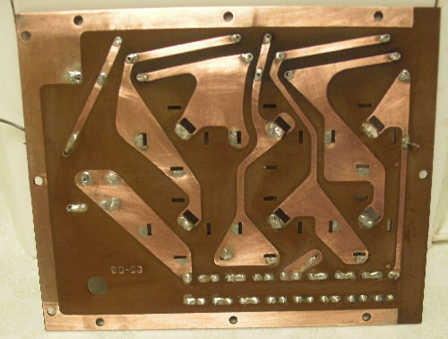
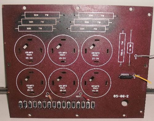
components and before cleaning. Image #4 shows the
bottom of the board before cleaning and image #5 shows
after. The same goes for the top of the PCB.
As you can see from the images 6 and 7 there's
nothing I can do about the burn or heat marks left on
the board which was cause by heat from the 30K 7 watt
bleeder resistors.
I replace the 30K 7 watts bleeder's with 30K 10 watts
resistor because this it what I had on hand. I
should have replace them with another type of resistor
what would product much least heat and a lower
wattage. Since the power supply section of the
amplifier will not be enclose and will
be rack mounted the heat will not be trap inside the
case. Hopefully this will help to keep things cooler.
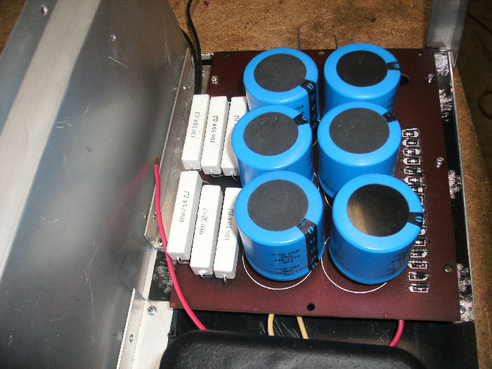
The original 16 rectifier diodes were replace with
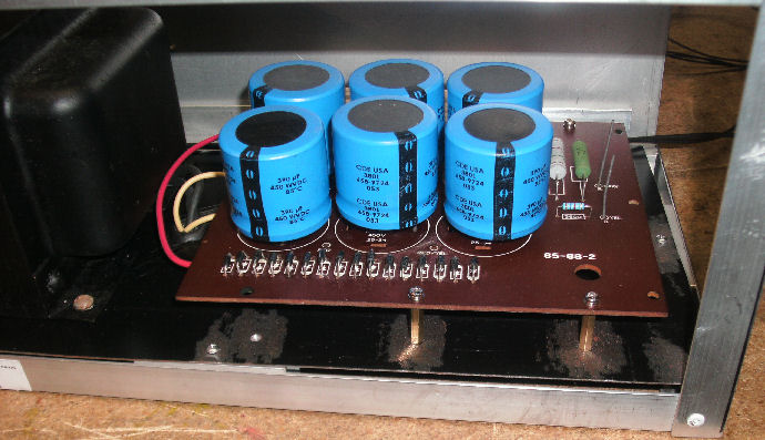
1N4007 diodes. The capacitor bank are 390uf 450 volts.
The reason I choose this value was to stiff up the
voltage and in turn to keep from having a big voltage drop under
full load.
Pictures 8 and 9 show how the newer capacitors were
fitting to the old PCB. I used the ends from some very
old resistor I have. Cutting the ends of the resistors
and then wrapping them around each leg of the new
capacitors and then soldering them to the old sb-200
PCB. This was not my idea I have seen this on another
site some where.
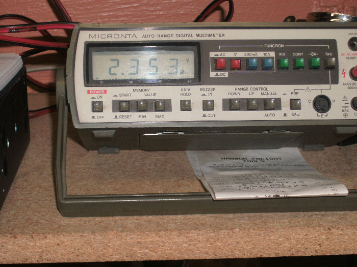
Testing The Board:
Next step was testing out the PCB board. Looking at pictures 10 and 11 you can
see with 124.8 volts ac input the supply is delivering
2,335 VDC
out. My line voltage vary from 122vac to 125vac.
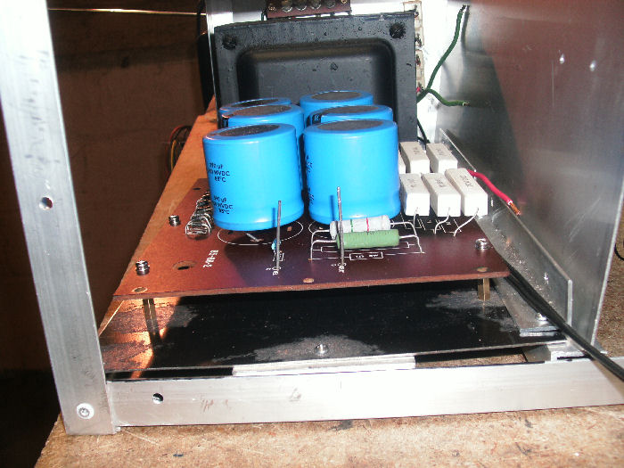
New Components:
Pictures 12, 13,14,15 shows the capacitor board with
all new components added.
This is just a re-built SB-200 power supply with bigger
components. The schematic is the same other then some
small changes.
Clicking on a image will
give a larger view. You may have to scroll down the
screen a bit to view. Still trying to figure out how
to fix this. |
|

Heathkit SB-200 Transformer
|

SB-200 PCB (1)
|
SB-200 PCB (2)
|
SB-200 PCB (3)
|
Bottom Before Cleaning (4)
|
| |
After Cleaning (5)
|
Top After Cleaning (6)
|
Top After Cleaning (7)
|

(8)
|

(9)
|
| |

HV Test (10)
|
HV Test (11)
|
New Parts (12)
|
New Parts (13)
|
New Parts (14)
|
| |
|
|
|
|
|
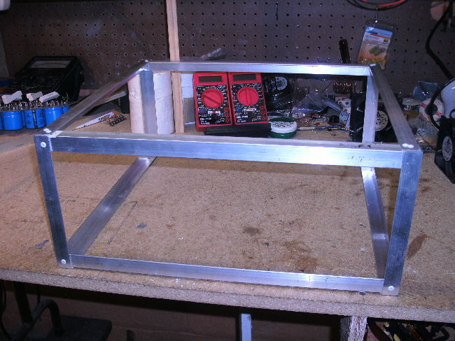
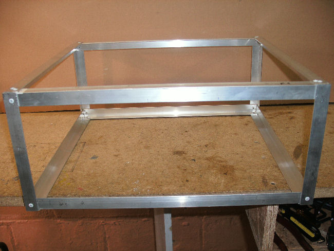
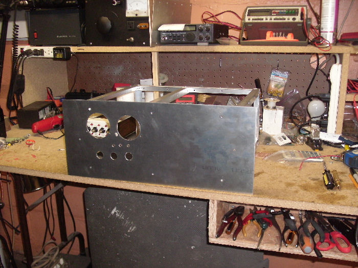
Chassis
Construction:
I won't going into
a lot of detail on how to build a chassis as this
is all up to the builder. I will show some details
was to what I did. I must say this. You will
need to
put a lot of though into your construction. And
where your going to mount your parts ahead of time. And try to drill out
most of your holes before
placing them into the chassis if possible. I used
aluminum angle for my frame work. Also found
a large piece of steel sheeting that I think came
out of some type of
locker of file cabinet laying around at work. This
was used to make the bottom panel in the chassis. I had to
cut the bottom sheet into two piece because after putting the frame
work together, I
could not place the hole bottom panel in place. The
frame work was all riveted together. The
aluminum angle was purchase from Home Depot. The
aluminum used to make the
rack mount front panel was purchase from Metal By The
Inch. You can do a internet search to fine them.
And there price's
I fine to be must better other online metal companies.
So far I have found a few miss stack in my own
construction but I can work around them LOL. Still
learning. |
|
Frame Work (1)
|
Frame Work (2)
|

Frame (3)
|
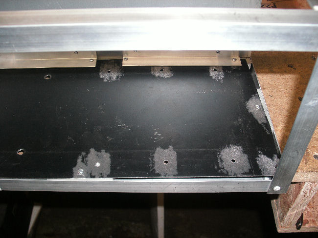
Bottom Plate In Frame (4)
|

Capacitor Placement (5)
|
|
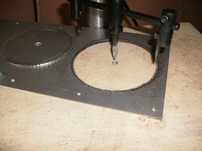
Cutting Hole for Fan (6)
|
Meter & Switch Hole Cut (7)
|
|
| |
|
| |
|
|
|
|
|
Miscellaneous Stuff:
Plate Voltage & Plate Current
Metering:
I put together a voltage dropping resistor for
the HV metering circuit which consist of (4) 750k ohm 3 watt
resistor for a total of 3 meg ohm. The resistor are
connected in series. This is so the
meter will read up to 3kv DC. Fig 1 show the dropping
resistors on perforated board with stand off soon to
be mounted. Fig 2 shows meter with the original scale.
Fig 3
Plate voltage and plate current meter with new scale.
Fig 4 Grid current meter with new face plate.
All meters are
0-1ma purchase from All Electronic Corp.
Fig 5 Plate Choke: The plate choke is home brew, wound
with number 22ga enamel wire about 55 turns on a
Fig 6 Filament Choke: Filament choke is also homebrew
on a 7 1/2" ferrite rod. You don't need this long of a rod
it's what I had on hand. Has you can see from the picture
I'm not using the
complete rod. The rod is wound using #14ga house wire some
40 turns using tie wraps to hole the ends together.
|
|

Meter Dropping Resistors (1)
|

Meter Dropping Resistors (2)
|
Picture To Be
Added
Meter With New Scale |
Picture To Be
Added
Meter With New Scale |

Plate Choke (5)
|
|
| |
|
|
|
|
| |
|
|
|
|
|
|
|
|
| |