|
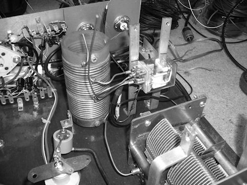
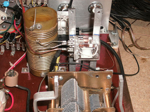
Tuning Network:
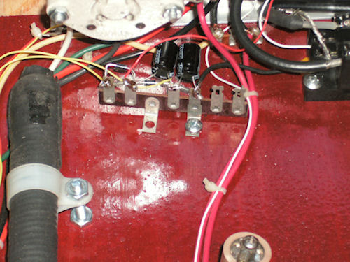
There's a voltage doubler
circuit that's used to supply 12 volts to each of the two
relays. One relay is used for transmit and receive switching.
The other is used for band switching between 30 and 40
meter band. The band switching relay which you'll be able to
see from the photos is mounted just under the plate tuning
capacitor. One of the 6.3v winding off the
transformer is used to supply voltage to the doubler circuit.
Voltage measurement were taken and I'm getting about 18vdc
from this circuit with no load. Also the transmit led lamp and
power on lamp and band switch indicator lamp are getting power
from this circuit. Band switching is control by a rocket
switch on the front panel along with a led lamp to let me know
when the amp is in the 40 meter position.
I'm not using a tune input circuit. My Yaesu FT-950 has a
built in antenna tuner in it so I'm using it to tune the input
of the amplifier.
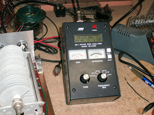
Before the band switching relay was wired up I did a check
on the output tuning network and all check out as you'll be
able to see
from the photos with swr being measure 1:1. After some testing with a dummy load
and on the air testing. It seem that I need to move the 30 meter
band tap 1 turn. As I found out that the plate tuning capacitor
was almost fully open.
The tank coil and the loading capacitor came out of my SB-200
amp.
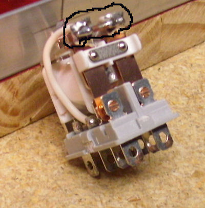
There's also a photo showing relays with both relay contact tabs solder
together with a small piece of #14 wire. Relays are DPDT 12v
at 10A.
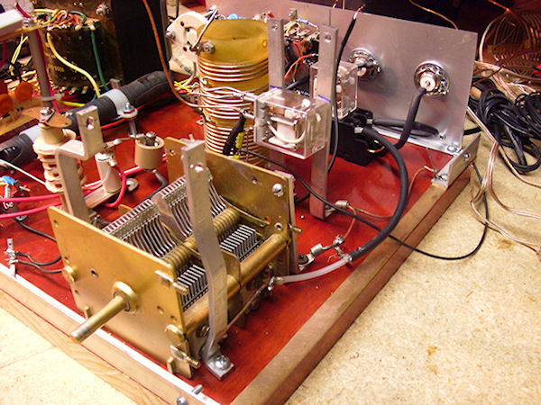
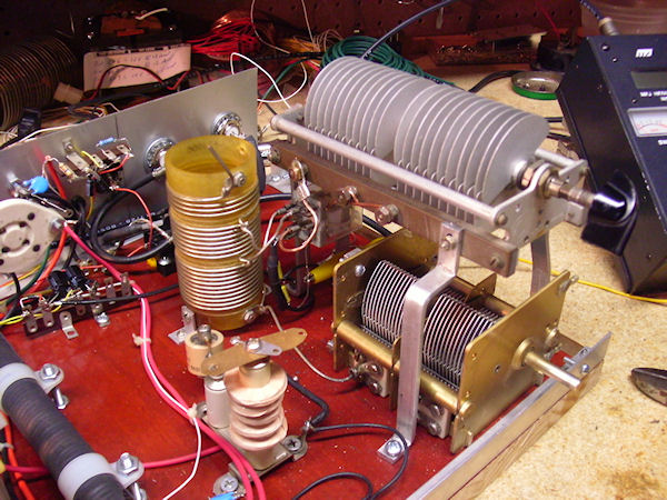
I made mounting brackets for the plate tuning capacitor.
Installed tank coil for the PI Network just off the side of
the tuning and loading capacitor. The tank
coil came out of my SB-200 amplifier.
Below you'll fine a image gallery of pictures of the
PI Network. Click on the thumb nail picture on the right to scroll through the
pictures. |