Step 1 -
Building The Power
Supply
The first thing I
started with was build and test out the power supply. And the first item to
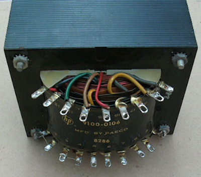
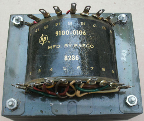
check out was the transformer to make sure it would be capable
of giving me the voltage's needed for this project. The
transformer can be operated at 120/220 volts. I'm using 120
volts at this time as I have no 240 line at this time. This transformer has lot of secondary voltages. A
550volts tap, (4) 6.3 volt taps and (1) 105v tap. This transformer
was taken from a discarded HP test equipment.
I spent about two days putting the rectifier board and the
filter capacitor board together. I tested each
board before connecting the two together, To be sure there were
no problems. Its much easier to trouble shoot any problems
before putting the two together.
The original circuit call for 1N3253 diodes in the rectifier
board. I used 1N4007 diodes. It also call for 1200v .01uf ceramic disk
capacitor. I used .01uf 2kv capacitor because that's what I had on
hand which will also give it more head room.
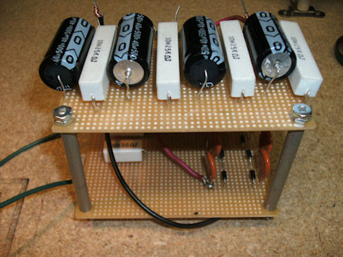
The filter capacitor board call for 40uf at 450volt. I used 40uf
at 500
volt. It took a little time to fine these on ebay. I came
across a ebay seller ((JustRadio)) that were selling different
electronic components and they carried the 40uf capacitor I
needed.
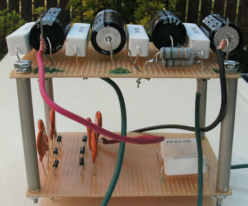
Both boards
were built on perforated board. I used thin aluminum tubing and
long treaded rods to make my standoff mounts for the rectifier
and capacitor board.
After
wiring both rectifier and filter capacitor board together
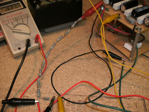
another test was done to measure the output voltage. A high
probe was made to allow me to test the high voltage supply. As
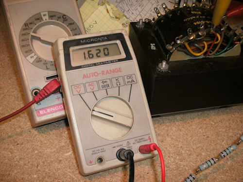
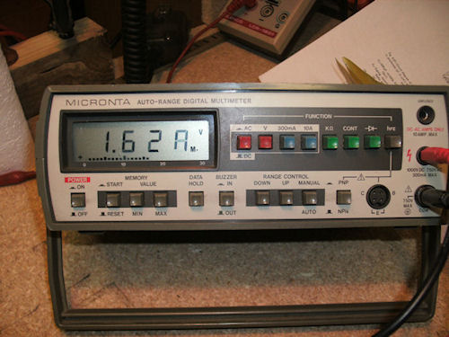
you can see from picture to follow. You can see from the two different meters the voltage test are
the same. Voltage measure 1650vdc with 122-125 vac line input.
The meter show 1620vdc that was because I was able to control
the input ac voltage with a homebrew varic supply. When
connected directly to the ac line I measure 125vac with
1650vdc out.
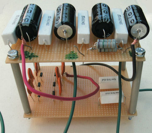
The standoff were made from some small aluminum
tubing I had on hand, and a small 3 foot treaded rod purchase
from home depot with nut was used to mount the two board
together. And some home made L bracket to attach the boards
to the base plate. Not having to drill holes in sheet metal
was great. Just screw everything right into the wooden base.
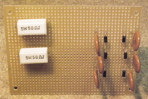
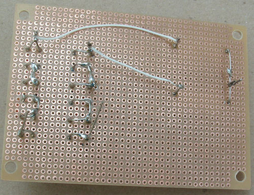
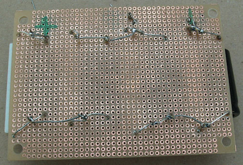
The rectifier board is made up with (6) .01uf ceramic disk
capacitor, (6) Diodes, and two 5 watt 50 ohm sand type
resistors.
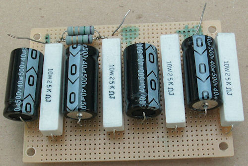
The filter capacitor board was made with (4) 10 watt 25K ohm
sand type resistors. and (4) 40uf 500 volt electrolytic capacitor.
The 4 resistor are used as bleeder resistor to drain the
electrolytic capacitor when the power is turn off.
This amplifier was constructed on some scrap 1/2 inch plywood
board cut from an old shelf I made sometime ago.
Below you'll fine a image gallery of pictures of the power
supply. Click on the thumb nail picture on the right to scroll through the
pictures. |